
Replacements · Field Guide
How to Measure HVAC Coils for a Replacement.
An accurate replacement starts with accurate measurements. Get the numbers right and your new coil drops in, connects to existing piping, and performs the way the system was designed to. Get them wrong and you are looking at field modifications, delays, and a unit sitting open longer than it should.
This guide walks through every measurement you need to order a replacement coil with confidence. If you would rather not do it alone, we have two easier paths.
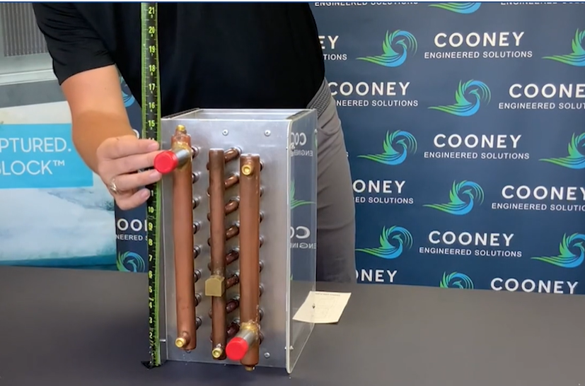 Measure twice
Step one
Start by Identifying the Coil Type
Knowing what kind of coil you are measuring determines which details matter for the replacement. Most commercial systems use one of five types.
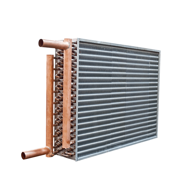
Fluid Coils
Hot water, chilled water, and glycol coils. Supply connections are normally at the bottom of the coil, return bends are visible, and the coil usually has vent and drain connections.
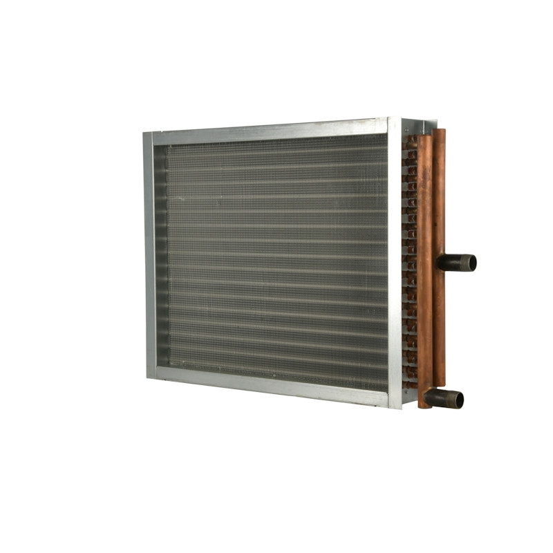
Standard Steam Coils
Supply and return headers, with the supply connection normally in the middle of the supply header and the condensate drain at the low point for complete drainability. Rows are limited to 4, connected by return bends. Same-end or opposite-end connection construction.
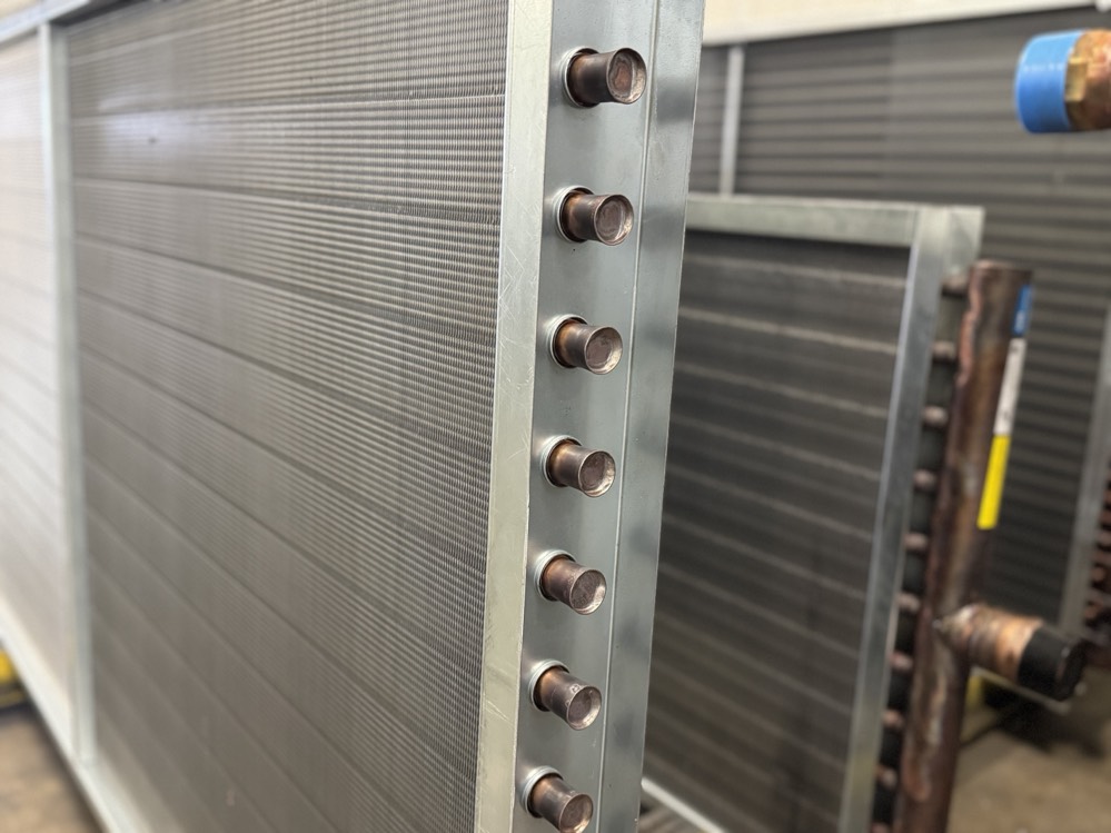
Steam Distributing Coils
Supply connections are normally in the middle of the header with no return bends. Rows are limited to 2 with 5/8" construction.
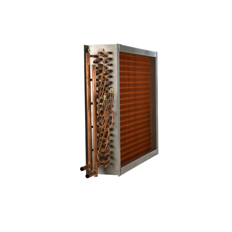
Direct Expansion (DX) Coils
DX and evaporator coils normally have distributor leads (spaghetti tubes) and expansion valves, and can have multiple distributor arrangements.
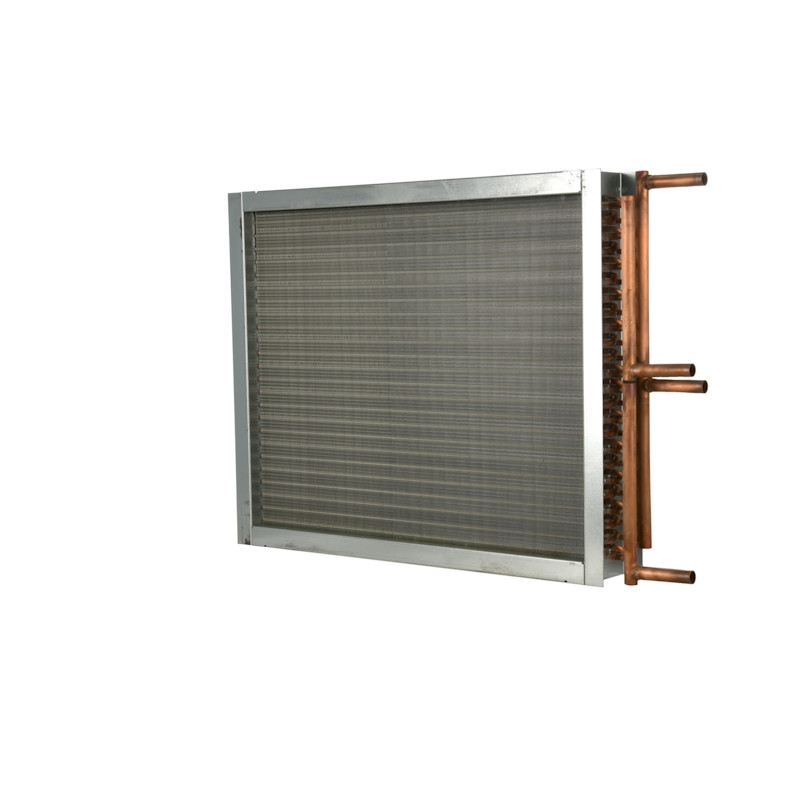
Condenser Coils
The supply connection normally enters at the top of the coil. These look similar to a water coil except for the supply connection location. Sub-cooler circuits typically have separate headers and represent a small portion of the coil surface.
Step two
The Measurements You Need
Work through these in order. A measuring template keeps you from missing one — download the templates here.
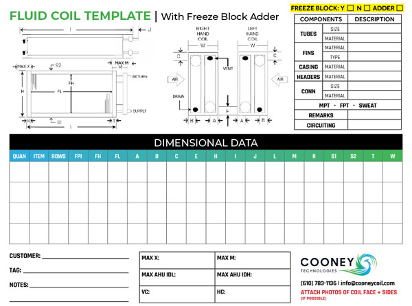
Finned Height and Finned Length
Finned height is always measured in the direction of the fin. Finned length is always measured in the direction of the tubes, regardless of which way the tubes run.
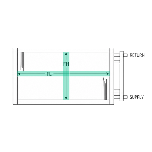
Casing Height
Measured in the same direction as finned height. Include the casing and sideplate flanges on the top and bottom of the coil. If the flanges are flat, you are measuring finned height plus metal thickness.
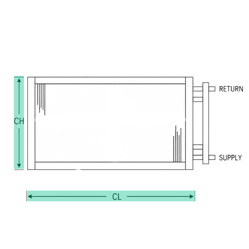
Casing Length
Measured in the same direction as finned length. Include the tube sheet flanges on the ends of the coil. Some coils have baffles covering the headers — include those in your casing length.
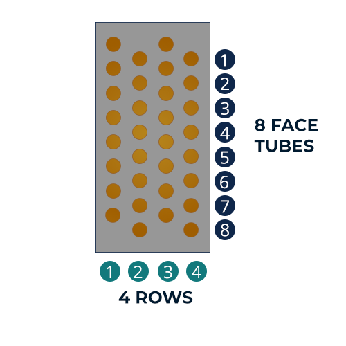
Number of Rows
Rows are always counted in the direction of airflow, regardless of how the coil is mounted. Count from the header end or the return bend end. Keep in mind that return bends or headers may run unevenly across the coil.
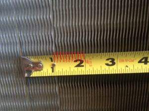
Fins Per Inch
Using a ruler or tape measure, count the number of fins within one inch. Normal fin counts run between 4 and 14 FPI.
Casing Depth
Measured in the direction of airflow. Casing depth typically runs 4" to 6" for hot water and steam coils, and 6" to 15" for chilled water and DX coils.
Overall Length, Including Headers
One of the most important dimensions, because most coils only have connection stubs extending outside the unit walls. Measure from the outside edge of the header end (not including connection stubs) to the outside edge of the return bend end, plus any baffles extending beyond the headers or return bends.
Overall Length, Including Connections
Add the length of the connection stub to the overall length. This matters for two reasons: some suppliers include connections within the casing length of the unit, and your piping cannot be moved.
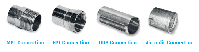
Connection Size and Type
Note your connection type, or the new connection needed if the system is being repiped. If necessary, remove insulation to see the incoming and outgoing lines, and measure the outside diameter of the line to determine connection size.
- MPT — male pipe thread, threaded on the outside
- FPT — female pipe thread, threaded on the inside
- ODS — sweat connection, no threads
- Victaulic — groove around the outside
Airflow Direction
Airflow is described by the direction air moves through the coil. If the coil is mounted vertically (on the wall), airflow is horizontal. If the coil is mounted horizontally (on the floor or ceiling), airflow is vertical.
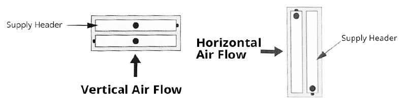
Tubes Per Row
Count the number of tubes in the first row. This matters when ordering an exact replacement.
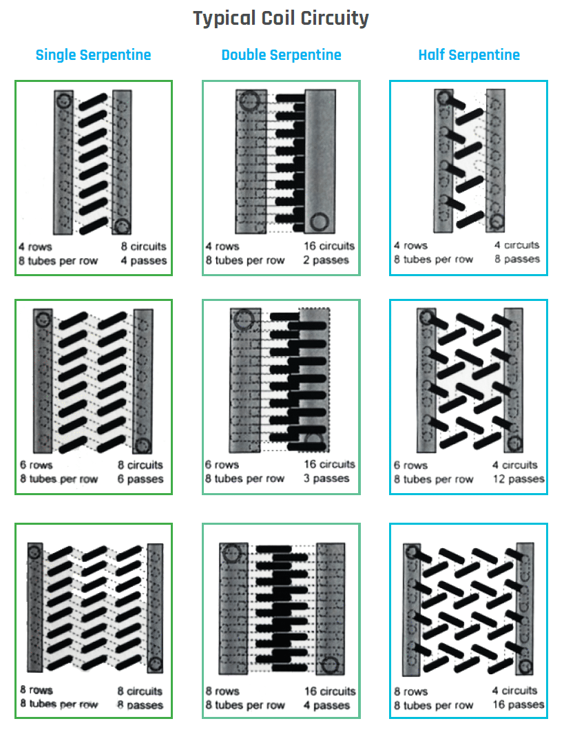
Coil Circuitry
Circuitry is the number of tubes feeding into the header divided by the number of tubes in the first row. Capture both counts: tubes in the header and tubes in the face.
Field notes
Tips From the Field
The more information the better
A measuring template makes it much harder to miss something.
Photos and video help
Set your phone camera to the .5 wide lens to capture tight spaces inside the unit.
Circuiting matters
Record tubes in the header and tubes in the face.
Capture the centers
Horizontal and vertical centers of pipe connections, plus the maximum length, height, and depth inside the air handler.
Silly putty works for FPI
In dark spaces, roll it out, press it against the fins, and measure the imprint outside the unit. Gum works in a pinch, but we do not recommend chewing it afterward.
Measure twice
Then write it down before you climb out of the unit.
Before you order
Want a Second Set of Eyes?
Measurements drive everything downstream. If you would rather have our team confirm them, we will come to your site, measure the coil, and review the replacement spec with you before anything gets ordered.
Next step
Send Us Your Measurements
Every replacement order at Cooney Technologies gets an engineering review before it goes to fabrication, so your measurements get checked against the application, not just transcribed onto a quote.
Have all 13 numbers?
Coil type · FH · FL · CH · CL · rows · FPI · casing depth · OAL · OAL with connections · connection size and type · airflow direction · tubes per row · circuitry.